The details in ISO surface finish standards relate to surfaces produced by abrading casting coating cutting etching plastic deformation sintering wear erosion and some other methods. Callouts and symbols used for different surface finishes can be slightly different so well look at a couple.
Complete Surface Finish Chart Symbols Roughness Conversion Tables
Click Insert Surface Finish.
. I have a drawing from a Designer in which 2 at the end of a bore needs to be rough. The first row of numbers and letters within the roughness symbol is a specification for surface roughness on a fine scale. I mean you could see the tear marks where the tool was plowing the material off.
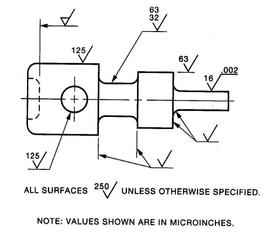
There are many variations of the surface texture symbol but most often it is used with a microinch or micrometer value callout that specifies the roughness of a surface. Surface Roughness Finish Surface roughness - a measurable characteristic based on roughness deviations Surface finish a subjective term Arithmetic Average AA Ra arithmetic mean value of roughness y the vertical deviation from nominal surface L mthe specified distance Root-mean-square RMS the square root of the mean of the squared deviation over. Drawings - Hole callouts Chamfer edges Surface texture etc Ive moved across to Fusion 360 from creo parametric and solidworks.
Surface Finish Correlation between Ra Rz and Tp bearing surface ratio General Measurement Device and Calibration Topics. It does not change. Click anywhere in the white space of the drawing Click a point on the edge of a circular view Enter more descriptions in the dialog if desired and place more symbols.
The principal ISO standard that specifies surface roughness is ISO 1302 and defines the surface roughness symbology and additional requirements for engineering drawings. Section 631 above described parameters using lTnN However no information was given concerning how these are added to features on a drawing. Interpreting this figure is easier than it might look at first.
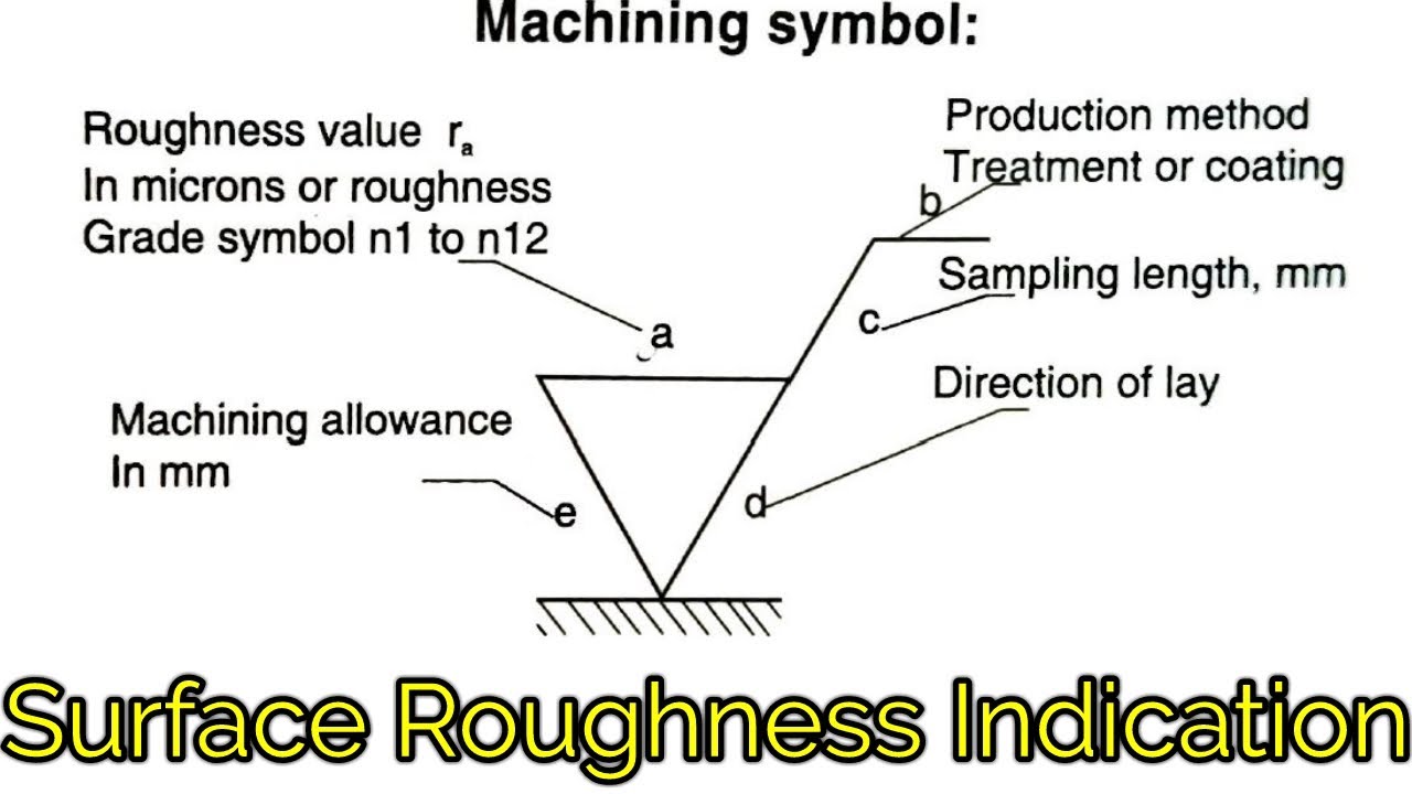
Method of indicating surface finish and texture. This handout will focus on the standards of annotation for fasteners and hole callouts local notes. They were just simple stepped reducers that were turned down.
In the drawing just the inch dimensions are shown but not written which thread like UNC etc. Definition GDT Clarification - Callout for Profile of a Surface Reference to the Datum. Pick InstSelects a symbol by picking an instance of the symbol in the drawing.
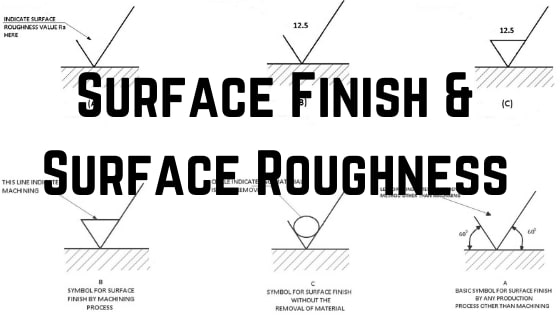
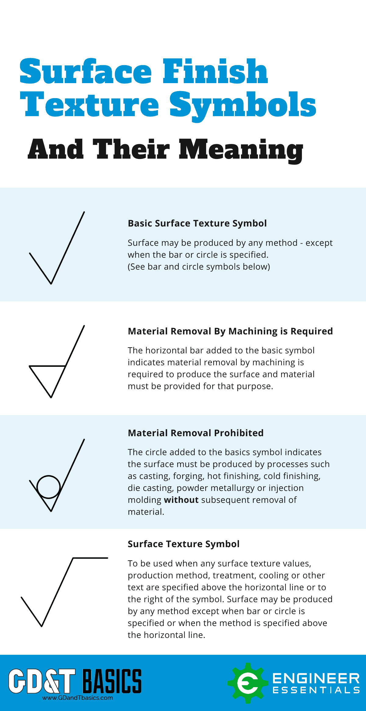
With some threads it works on what does this depend. The quality of a surface finish on a metal surface produced by production method other than machining is shown on the drawing by a tick symbol as shown in fig-A. Click when finished or to cancel.
It is based on what is termed a tick symbol that defines the SF and points to the surface in. In the United States surface finish is usually specified using the ASME Y1436M standard. Surface finish callouts on drawings.
General Measurement Device and Calibration Topics. Manufacturing and Related Processes. Surface finish would describe processes like anodizing electroplating or painting.
The methodology to do this is described in ISO 13022001. Profile of a Surface Callout on this Drawing. A symbol for defining the surface finish of a part.
Free easy returns on millions of items. One of our local vendors ex-vendor now BTW recently did some 303 SS parts for us. To add a leader right-click the symbol and select Add leader.
Free shipping on qualified orders. Extracted to 2D drawings. For some situations having a surface that is too smooth is not acceptable.
Many of these elements are notational in nature. When I create a UNC thread in the model. For ISO and related drafting standards you can display surface finish symbols per 2002 standards by selecting Display symbols per 2002 in Document Properties Surface Finishes.
I have to two questions about the drawing standard. The rest of the world commonly uses International Organization for Standardization ISO 1302. The area is indicated and has a callout saying APPROX 005 ROUGH LATHE MARKS IN HATCHED AREA INSIDE PART.
Ive been suprised how difficult some things are to achieve when creating a drawing of a part. Symbols Used In GDT Callouts Basic Dimensions Basic dimensions represent a theoretically perfect feature or size. Callout on Surface Finish.
It is a measure of the complete texture of a products surface that is defined by three characteristics of surface roughness waviness and lay. I tried to add entries in the. KEYENCEs Introduction to Roughness website introduces parameters and case studies related to such surface measurements.
The tolerances were fine but surface finish was the worst I EVER saw. Drawing Standards thread callouts surface finish symbol production. Surface finish Evaluation Length Inspection Prints Drawings Testing Sampling and Related Topics.
Surface finish refers to the process of altering a metals surface that involves removing adding or reshaping. The surface roughness is the measure of the total spaced irregularities on the surface. General Measurement Device and Calibration Topics.
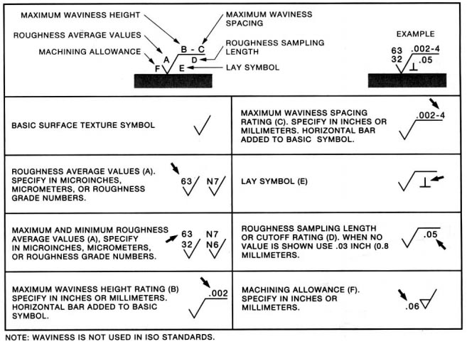
Surface finish symbols are formed by combining the Symbol and Lay Direction direction of lay. Roughness affects various part characteristics including the amount of wear the ability to form a seal when the part makes contact with something and the ability to coat the part. Surface Finish - Callout as 8 - 16 Rq.
Surface Finish Symbols Callouts and Standards. The GET SYMBOLmenu appears. If you have an area where you want deliberately rough surface finish in my case to scatter light is there a standard way of saying it.
Read customer reviews find best sellers. This basic symbol consists of two legs of unequal length. These are inclined at approximately 60 degrees to the line representing the surface to be machined with the vertex touching it.
To Add a Surface Finish Symbol. Ad Browse discover thousands of brands. You can select the face in a part assembly or drawing document.
Annotation standardization is provided by the ASME. Some examples include thread specifications surface finishes surface quality and dimension tolerances. NameSelects a symbol from the SYMBOL NAMESmenu containing a list of symbols that are currently in the drawing.
The trianglelong division symbol roughness symbol is the basis for the callout. Click in the drawing to place the symbol and surface finish descriptions. Surface texture callouts can be very complex or very simple depending on what is required in the finished product.
Select one of the following. And surface roughness would not include characteristics like waviness or lay.
Complete Surface Finish Chart Symbols Roughness Conversion Tables

Surface Finish Wikipedia

Surface Roughness Symbol In Drawings Mechanical Engineering General Discussion Eng Tips
Surface Roughness Indication Symbols Surface Roughness Symbol Indication In Hindi Youtube

Complete Surface Finish Chart Symbols Roughness Conversion Tables Surface Surface Finish Symbols Surface Finish
Surface Finish Surface Roughness It S Indications Symbols
The Basics Of Surface Finish Gd T Basics
Iso Surface Roughness Symbols Terminology
0 comments
Post a Comment